Operation Manual
Introduction
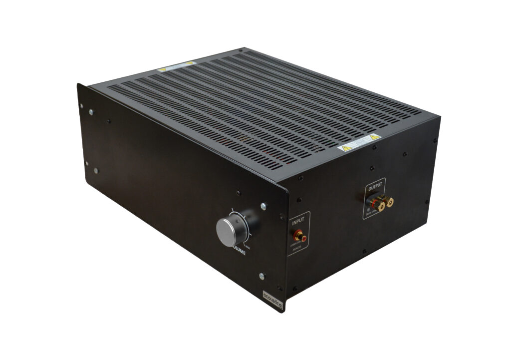
Acoustico tube power audio amplifier was designed as a single channel, high fidelity analog audio device. The amplifier reproduction is sonically transparent and absolutely accurate. Now you can take advantage of Acoustico’s commitment to product excellence which is represented by this amplifier. The amplifier delivers an optimum audio performance when deployed with the Acoustico speaker cable and speaker. It is well-suited for use in multi-channel home audio systems like home theaters or stereos. The amplifier is manufactured at the Acoustico facility in Central Illinois, USA. Below are the pictures of the amplifier.
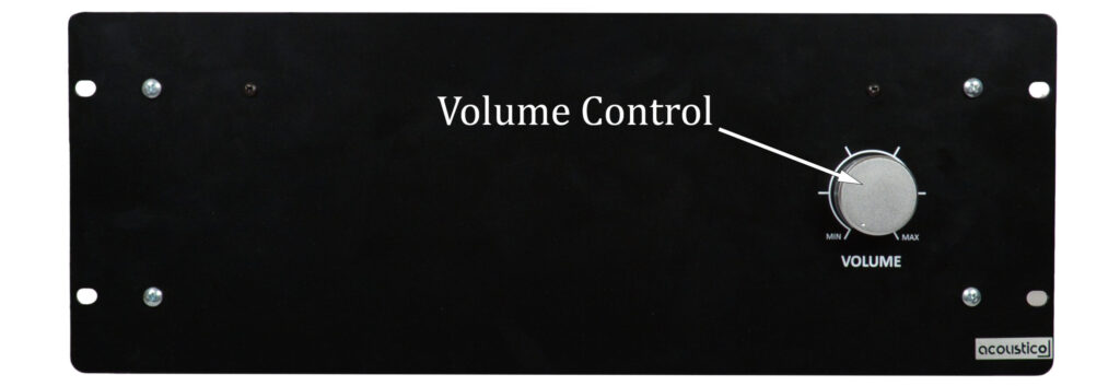
Front Panel Controls (see picture below)
Motorized volume control was designed for manual or remote control (if equipped) operations.
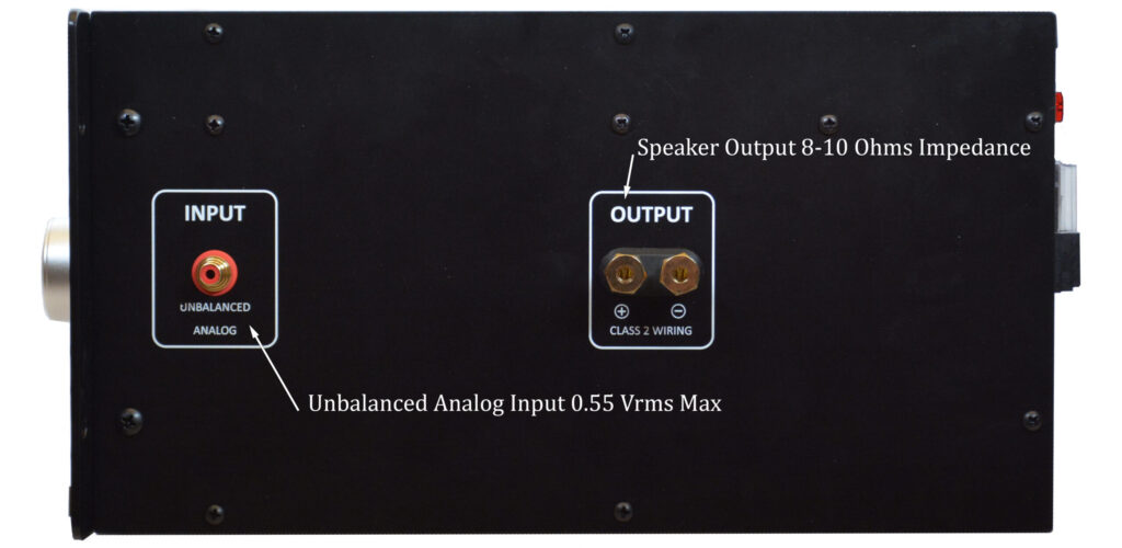
Right Side Panel Connections (see picture below)
INPUT, unbalanced analog for connecting an unbalanced audio cable with an RCA male connector to a low distortion audio signal source with impedance and output to not exceed 600 ohms and 550 mVrms respectively for all frequencies from 20Hz to 20,000Hz.
OUTPUT for connecting a single speaker with a nominal impedance ranging from 8 to 10 ohms measured at 600 Hz.
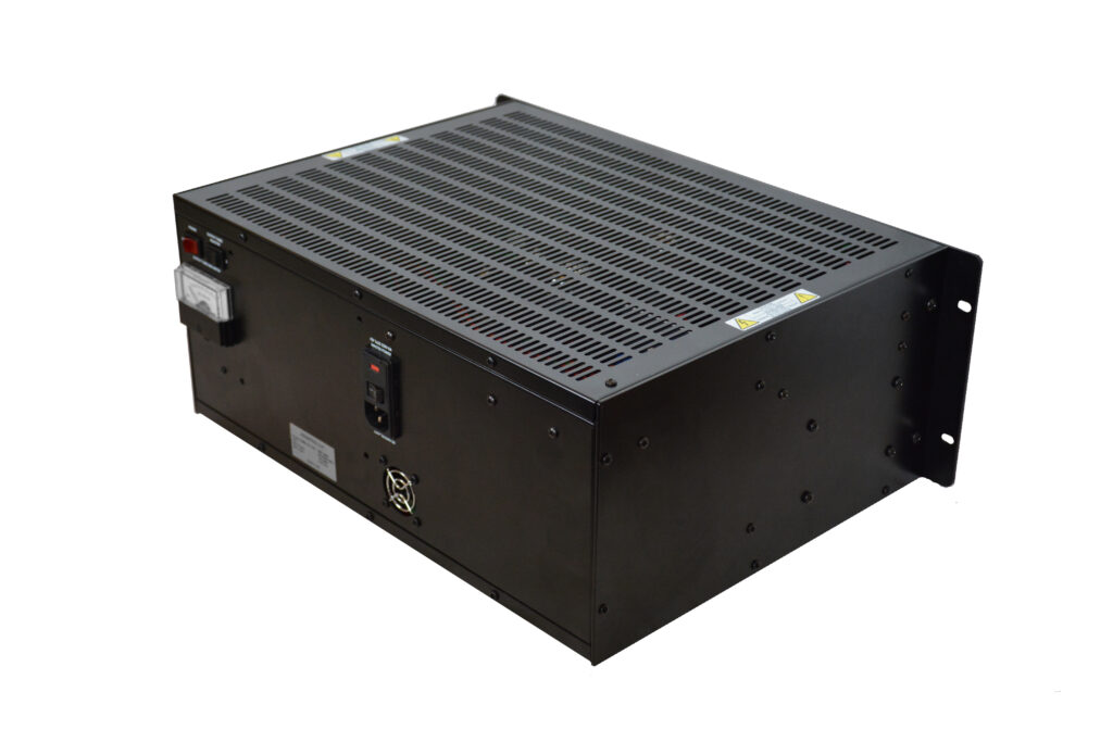
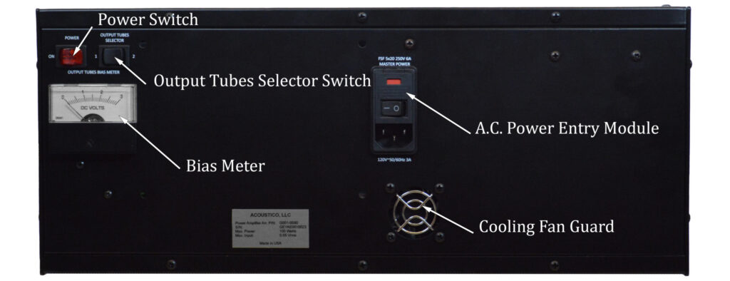
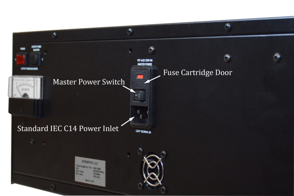
Back Panel Switches, Bias Meter, A.C. Power Entry Module, Cooling Fan Guard (see picture below)
The power switch turns the amplifier on/off. When the switch is in “off” position, it enables the remote control (if equipped) to turn the amplifier on/off.
The selector switch for output tubes toggles the bias meter between two of them.
The bias meter helps to verify that the output tubes are operating as designed.
A.C. power entry module is intended for connecting the amplifier to the mains a.c. power.
The cooling fan guard protects the fan from damage.
Features
Power Output
The Acoustico single channel tube power audio amplifier is capable of 100 watts into an 8 ohm speaker with less than 1.0% distortion for all frequencies from 20Hz to 20,000Hz.
Fixed Bias Output Stage
This configuration reduces intermodulation distortion and improves transient response.
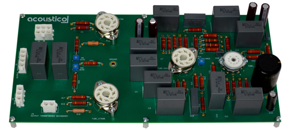
Proprietary Circuit Boards (see picture below)
Acoustico has developed circuit boards that can handle high currents and voltages that are prevalent in tube electronics, and shield the audio circuits.
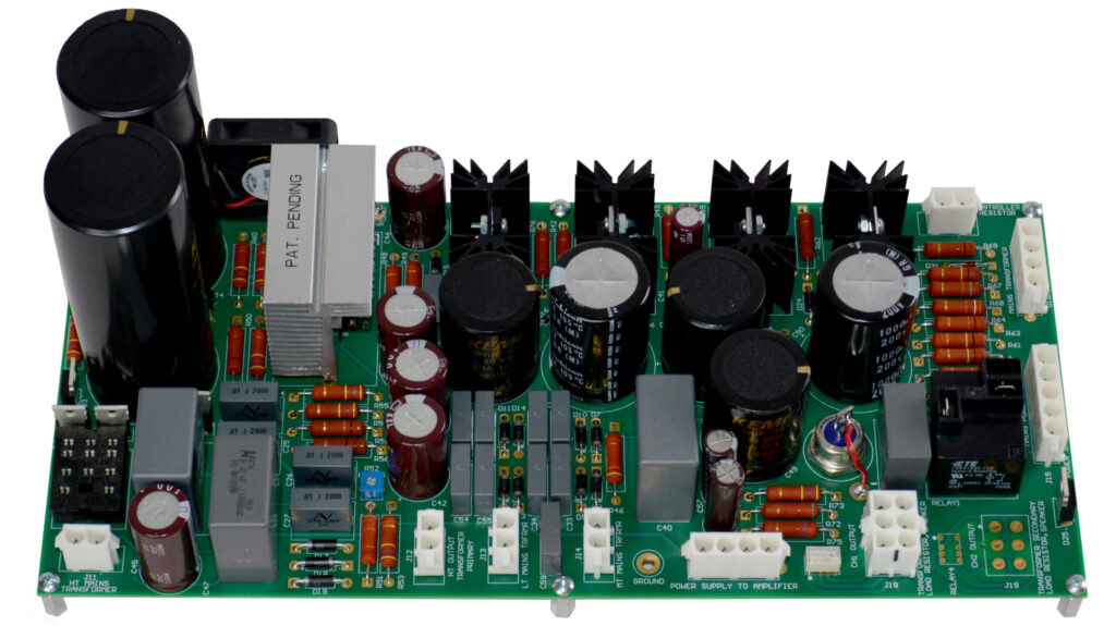
Proprietary Power Supply (see picture below)
A uniquely designed power supply includes an Acoustico developed power transformer and high, bias, and low voltage regulators. The regulated voltages ensure the long term optimum performance of the tubes. The power supply delays high voltage application to the tubes until the cathodes reach nominal operating temperatures. It also protects the output tubes from potentially destructive high levels of currents flowing through them in case of their bias voltage loss. In the event this occurs, the high voltage is removed from the tubes. The power supply also delays the connection of the output transformer to the speaker. This delay is necessary for preventing any sound related to transients when high voltage is first applied to the tubes. It disconnects the output transformer from the speaker prior to turning the power transformer off. This also eliminates any sound related to transients when high voltage is first removed from the tubes. The power supply also disables the power transformer when the top or right panels are removed. However, the mains a.c. voltage is still present in the amplifier even if the power transformer is disabled unless the power supply cord is unplugged from the mains a.c. receptacle.
Unbalanced Input
The amplifier has a single unbalanced analog input.
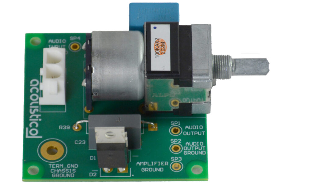
Motorized Volume Control (see picture below)
Acoustico has designed a special volume control that can be operated manually or remotely (if equipped).
Gold-Plated Connectors
Gold-plated input jack and output binding posts provide trouble free connections.
Bias Meter
The meter is necessary for monitoring performance of output tubes.
Enclosure
The enclosure is made out of aluminum coated with EBL powder flat black matte finish. The enclosure provides electrostatic shielding for all audio circuits.
How to Operate
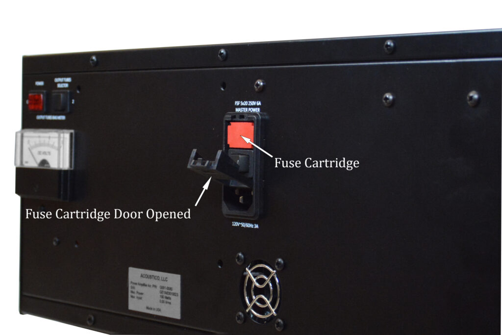
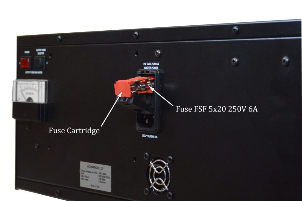
A.C. Power Entry Module (see pictures below)
The power entry module provides two element EMI filter for amplifier protection. The entire module is covered with metal, shielding the filter from RFI coupling, and covering the mounting cut-out to block RFI entering the amplifier. The module is rated for 10A, 250VAC, 50/60 Hz. It includes a single FSF 5×20 250V 6A main fuse, master power DPST on/off switch and standard IEC 60321-1 C14 power inlet. The master power switch completely disconnects the amplifier from the mains a.c. power.
Remote Control (if equipped)
The remote control is enabled when the mains a.c power receptacle is connected to the a.c. power entry module using the power supply cord (included with the amplifier), and the master power switch is in “on” position. The remote control turns the amplifier on/off and regulates the volume. In order for the on/off function of the remote control to work, the power switch should be in the “off” position. The remote control can still change the volume when the power switch is in either “on” or “off” positions.
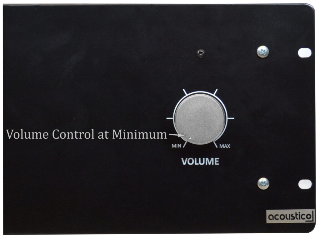
Motorized Volume Control
The volume control regulates the amplifier power output either manually or using the remote control (if equipped). When used with the remote control, the knob rotates as the volume is being changed. The control retains the volume level since the last use. A small polished indicator dot on the volume knob and dial printed on the front panel provides visual indication of the volume level.
Power on
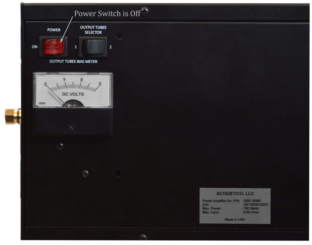
Before turning the amplifier on, please click the link to our page, Setup of Tube Power Audio Amplifier. The master power switch should be in the “on” position. The volume should be off before turning the amplifier on. This is accomplished by rotating the volume control knob to min (see picture below) position either manually or using remote control (if equipped). After that, the amplifier can be turned on in two ways: by either using the power switch on the back panel or the remote control. The power switch is illuminated. When the amplifier is turned on by the switch, the light inside comes on (see picture below). In order to turn the amplifier on using the remote control, the power switch should be in the “off” position (see picture below).
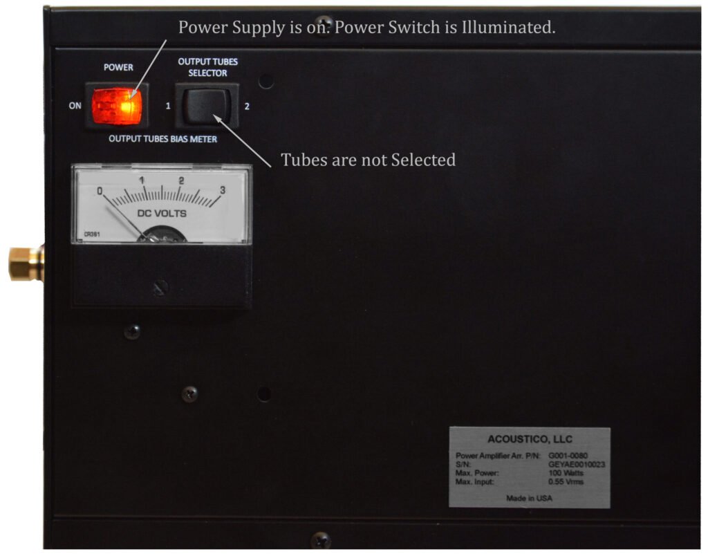
If either the top or right side panels are removed, the power transformer is disabled and the amplifier will not turn on. However, the power supply can still be powered up by either the power switch or remote control, assuming that the master power switch is in the “on” position. In this case, the power switch will be illuminated if the power supply is turned on by the power switch. The volume can still be changed either manually or by remote control.
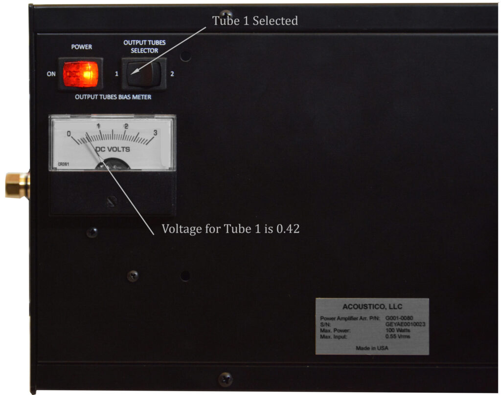
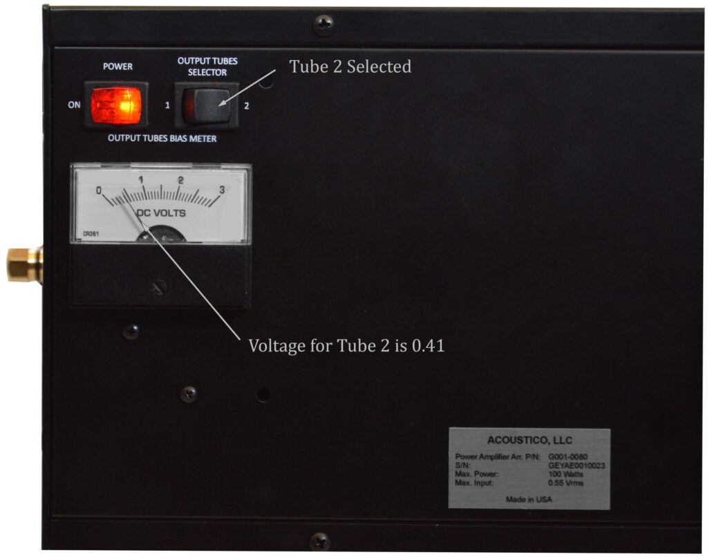
When the amplifier is first turned on, the power supply goes through the following sequence. The power transformer turns on after about 2 seconds and immediately powers up the low and bias voltage regulators, tube heaters, and high voltage regulator cooling fan. About 1 min later, the high voltage regulator is powered up and high voltage is applied to the tubes. About 15 sec after that, the output transformer is connected to the output binding posts. Normally, it takes up to 30 min for the tubes to reach optimum performance. However, the amplifier can be used within this time with the maximum power output of about 10W. It takes longer for the output tubes to fully warm up. Therefore, when the bias meter measures the voltages between 0.40 to 0.51 volts for each output tube (see pictures below), the amplifier is ready for use at rated power. In order to measure the voltages, the volume control should be at minimum, and the selector switch for output tubes should be in either position “1” or “2”. Numbers “1” and “2”, printed on the back panel next to the selector switch, identify the output tubes (see pictures below).
Power off
When the amplifier is turned off, the power supply goes through the following sequence. The output transformer is disconnected from the output binding post in about 2 seconds. Then, about 15 seconds later, the power transformer is turned off.
Technical Description
The Acoustico engineering staff has created a tube power audio amplifier without compromise, using the most advanced Acoustico circuit design concepts. Creating a tube amplifier with a high level of performance did not come easily. Many months of Acoustico proprietary computer simulations, design, testing, and measuring were required. Extensive controlled listening tests, the ultimate form of measuring, were conducted before the final design was accepted.
The design philosophy behind the amplifier development was to make the amplifier rated power output at least 10 times greater than what is required for most home listening spaces. It is a well-known fact that the distortions introduced by the tube amplifier are inversely related to the power output. Therefore, our amplifier is operating most of the time in the linear part of the gain curve. Also, having a high-rated power output ensures plenty of head room before clipping the audio signal. The amplifier topology was chosen to produce the most efficient, precision analog device. Every stage of voltage amplification was made as linear as possible. In order for the amplifier output to be flat for all frequencies from 20Hz to 20,000Hz, the circuits of every amplification stage were designed for minimizing the effect of tube shunt capacitances and resistance-capacitance couplings.
To greatly improve the signal-to-noise ratio and dynamic range that today’s audio demands, the amplifier power supply utilizes an Acoustico developed power transformer, and regulators for high, bias and low voltages.
Amplifier layout (see picture below) contributes to low operating temperatures by enhancing convection cooling. This ensures the long trouble free performance.
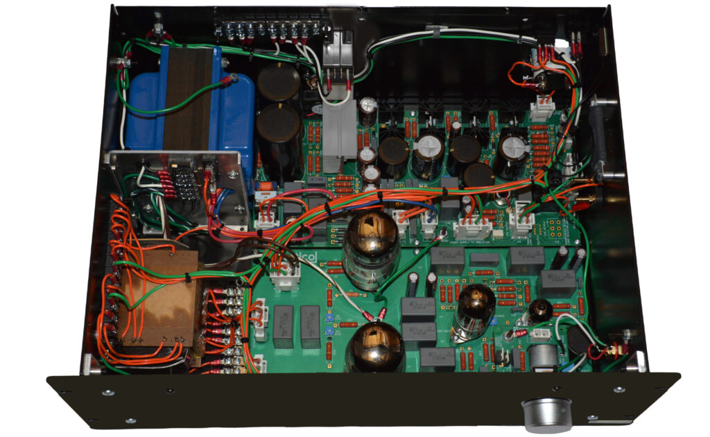
A power semiconductor which is used in a high voltage regulator, however, is cooled by a fan installed on the heat sink since the convection cooling is not enough for this circuit.
Precision metal film resistors and low dielectric absorption film capacitors are used in all circuits. All amplifier components, except tubes, are rated for 10,000 hours of operating life.
Specifications
Power output
100 Wrms into 8 ohm load
Output load impedance
8 ohms
Rated power band
20Hz to 20,000Hz
Total harmonic distortion
1% maximum at rated power
Frequency response
+0.05, -0.11dB for all frequencies from 20Hz to 20,000Hz
Input sensitivity (for rated output)
0.55 Vrms Unbalanced
Signal-to-noise Ratio
98dB below rated output
Damping factor with connected Acoustico speaker, for all frequencies from 20Hz to 20,000Hz
Greater than 10
Input impedance
90,000 ohms
Power requirements
120 Volts, 50/60Hz at 3 Amps
Standby (if equipped with remote control)
1 watt
Width
19 inch
Height
7.25 inch
Depth
14.5 inch
Weight
30 lb
The continuous improvement of its products is the policy of Acoustico Limited Liability Company who reserve the right to improve designs without notice.