Setup of Tube Power Audio Amplifier
IMPORTANT SAFETY INSTRUCTIONS!
Please read the information below before you start using your new tube power audio amplifier.
WARNING:
THE AMPLIFIER IS DESIGNED FOR 120V 50/60HZ MAINS A.C. POWER. IT DRAWS UP TO 3A DURING NORMAL OPERATION AND UP TO 6A DURING INITIAL HIGH VOLTAGE STARTUP.
WARNING:
TO AVERT THE RISK OF ELECTROCUTION, DO NOT REMOVE TOP, BACK, SIDE, OR FRONT PANELS. NO USER-SERVICEABLE PARTS INSIDE.
For servicing the tube power audio amplifier, please email Acoustico at eugenegrinberg@acoustico.llc. Servicing is required when the amplifier has been damaged in any way. This includes damage to the power supply cord or plug, from fluids, or from objects that have fallen into the amplifier. Servicing is also required If the amplifier has been dropped or does not operate as designed.
WARNING:
DO NOT DEFEAT THE SAFETY PURPOSE OF GROUNDING-TYPE PLUG.
A grounding-type plug has two blades and a third grounding prong. The third prong is provided for your safety. If the grounding-type plug supplied with the tube power audio amplifier does not fit into the mains a.c. receptacle or extension cord, consult a licensed electrician for proper connection.
WARNING:
PROTECT THE POWER SUPPLY CORD FROM BEING PINCHED OR DAMAGED, PARTICULARLY AT THE PLUG AND CONNECTION POINT TO THE AMPLIFIER.
WARNING:
DISCONNECT THE POWER SUPPLY CORD PLUG OF THE AMPLIFIER FROM THE MAINS A.C. RECEPTACLE DURING LIGHTNING STORMS OR WHEN UNUSED FOR LONGER THAN A WEEK.
WARNING:
TO AVERT THE RISK OF FIRE OR ELECTROCUTION, DO NOT EXPOSE THE AMPLIFIER TO ANY FLUIDS (RAIN, MOISTURE, SPILLS, SPLASHING, DRIPPING) AND DO NOT PLACE IT NEAR ANY OBJECTS FILLED WITH ANY FLUIDS.
WARNING:
DO NOT BLOCK, EVEN PARTIALLY, ANY VENTILATION OPENINGS BY PLACING OBJECTS ON THE TOP OF THE AMPLIFIER OR IMPROPERLY INSTALLING IT.
For installation please use the instructions below.
WARNING:
DO NOT INSTALL THE AMPLIFIER NEAR OR DIRECTLY ABOVE ANY HEAT SOURCES SUCH AS RADIATORS, HEAT REGISTERS, STOVES, OR ANY OTHER EQUIPMENT (INCLUDING AMPLIFIERS) THAT PRODUCE HEAT.
WARNING:
ONLY USE ATTACHMENTS/ACCESSORIES SPECIFIED BY ACOUSTICO.
WARNING:
CLEAN ONLY WITH A DRY CLOTH.
WARNING:
DO NOT EXPOSE BATTERIES IN THE REMOTE CONTROL (IF EQUIPPED) TO EXCESSIVE HEAT SUCH AS SUNSHINE, FIRE OR THE LIKE.
When discarding the amplifier, comply with local rules or regulations. Batteries should never be thrown away or incinerated, but disposed of in accordance with the local regulations concerning battery disposal.
Installation
All tube power audio amplifier components, except tubes, are rated for 10,000 hours of operating life. It is conditioned, however, to adequate ventilation. Therefore, air flow through the cooling fan guard on the back panel and escape of warm air through the ventilation openings in the top panel must not be impeded.
Acoustico recommends placing the amplifier on an open table or shelf, free standing on its own four rubber feet. The picture below shows a typical installation in a living room with Acoustico speakers.
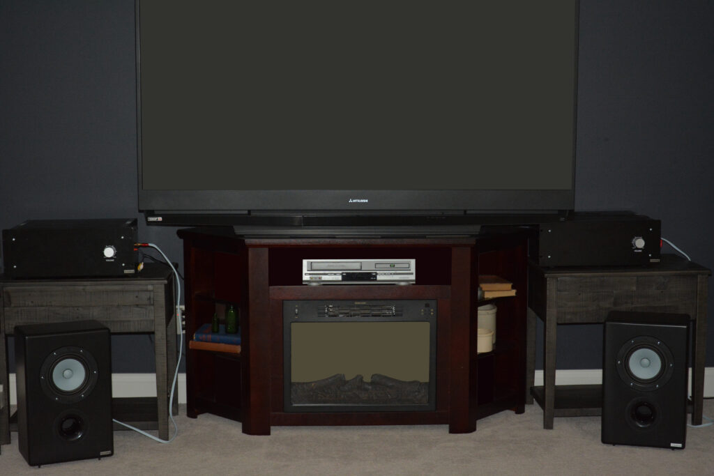
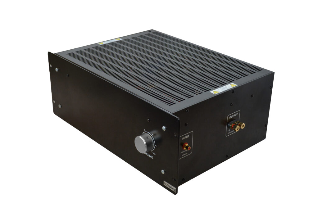
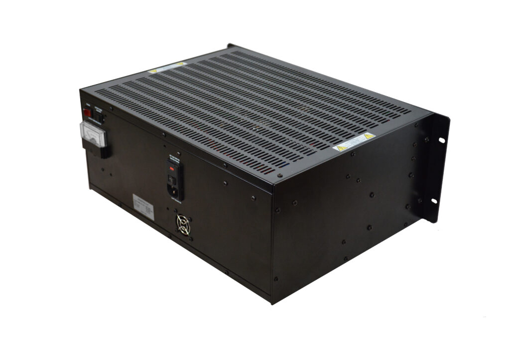
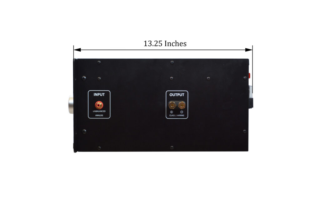
This type of installation ensures good air flow and enables easy access to the power switch (when the amplifier is not equipped with a remote control), selector switch for output tubes, bias meter, a.c. power entry module containing single main fuse, master power switch and IEC C14 male connector, output binding posts, and input RCA jack. The switches, meter, and entry module are all located on the back panel. Binding posts and RCA jack are located on the right side panel. The feet are glued to the bottom of the amplifier. They are not removable. Amplifier dimensions, switches, bias meter, binding posts and RCA jack are shown in the pictures below. The dimensions can assist in determining the best location for your amplifier.
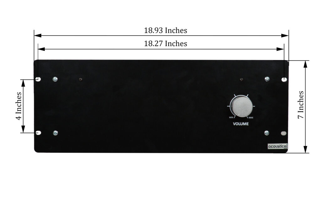
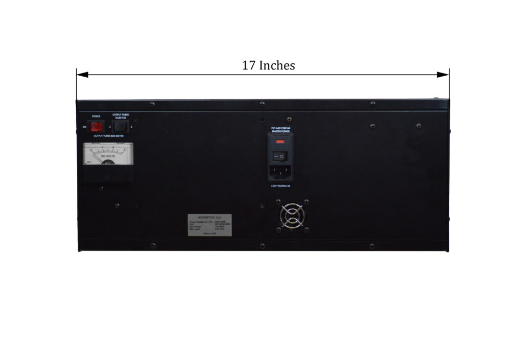
The amplifier can be also installed in a piece of furniture or custom cabinet of your choice. The amplifier is also designed to be hung in the furniture, cabinet, or rack by the front panel using mounting holes. Any of these installations should provide the following minimum spacing dimensions for cool operation and access to all switches, bias meter, a.c. power entry module, binding posts and RCA jack:
- 12 inches to the top panel
- 2 inches below the bottom panel
- 4 inches to each side panel
- 10 inches to the back panel
Connections
WARNING:
THE POWER SUPPLY CORD PLUG OF THE AMPLIFIER MUST NOT BE CONNECTED TO THE MAINS A.C. RECEPTACLE UNTIL AFTER SPEAKER CONNECTION HAS BEEN MADE.
FAILURE TO OBSERVE THIS WILL RESULT IN ELECTRIC SHOCK SINCE THE AMPLIFIER AND SPEAKER BINDING POSTS ARE HAZARDOUS LIVE.
ALSO, TURNING ON THE AMPLIFIER AND APPLYING AUDIO SIGNAL TO THE INPUT RCA JACK WITHOUT CONNECTING SPEAKER TO THE OUTPUT BINDING POSTS WILL DAMAGE THE OUTPUT TUBES.
WARNING:
THE NEGATIVE OUTPUT BINDING POST FOR CONNECTING SPEAKER ON THE RIGHT PANEL OF THE AMPLIFIER IS ABOVE ENCLOSURE GROUND.
DO NOT GROUND THIS BINDING POST OR CONNECT IT WITH ANY OTHER POWER AMPLIFIERS.
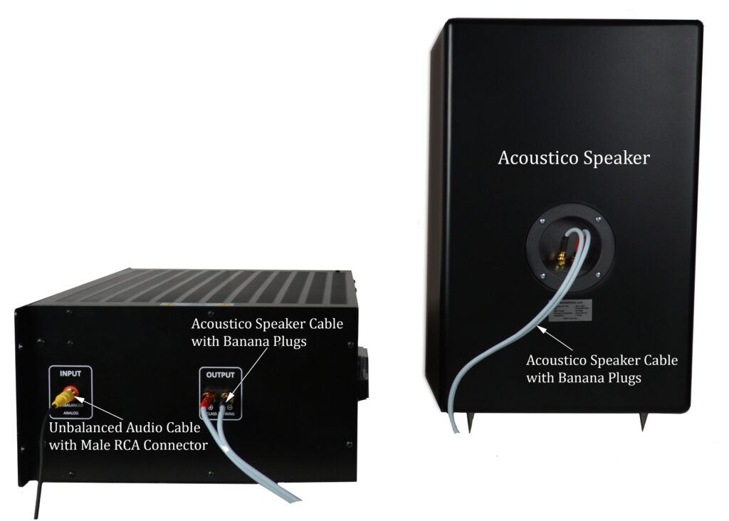
The tube power audio amplifier was designed for the connection of a single speaker with a nominal impedance ranging from 8 to 10 ohms measured at 600 Hz. For the best performance and safety, it is important to always match the impedance of the speaker to the amplifier. Therefore, we recommend the Acoustico speaker for use with our amplifier.
When connecting the speaker to the tube power audio amplifier, it is very important to use a cable of adequate size, so there is little to no power loss with minimum inductance and capacitance in the cable. Therefore, we recommend using the Acoustico speaker cable. The length and size of the cable were optimized for the home stereo system setup that can be accessed by clicking the link to our Speaker Setup page. The cable uses banana plugs that are inserted in the binding posts of the speaker and amplifier (see picture below). The polarities of speaker, cable and amplifier output must match to avoid sound cancellations.
The audio circuitry of the tube power amplifier was designed for precision amplification of an analog signal. For the best sound reproduction, a low distortion low impedance unbalanced analog audio signal source should be used. We recommend audio source impedance, including connecting cable, to not exceed 600 ohms. The audio source should be connected to the RCA input jack using an unbalanced audio cable with an RCA male connector (see picture below). The cable length should be no more than 5 ft. for minimizing shunt capacitances. A typical shielded unbalanced audio cable of this length would have shut capacitance of about 100 pF. The audio source impedance and cable shunt capacitance create a low pass filter. Therefore, the recommended cable length and source impedance ensure a flat amplifier output for all frequencies from 20Hz to 20,000Hz. The audio source output should be no greater than 550 mVrms to prevent excessive distortions at rated power output of the amplifier.
WARNING:
THE MAINS A.C. POWER SHOULD BE APPLIED TO THE AMPLIFIER ONLY AFTER AN UNBALANCED ANALOG AUDIO SOURCE AND SPEAKER ARE CONNECTED TO THE AMPLIFIER.
FAILURE TO DO SO MAY CAUSE A MALFUNCTION OF SYSTEM OPERATION AS THE MICROPROCESSOR’S CIRCUITRY FOR THE REMOTE CONTROL (IF EQUIPPED) IS ACTIVE WHEN THE MAINS A.C. POWER IS APPLIED.
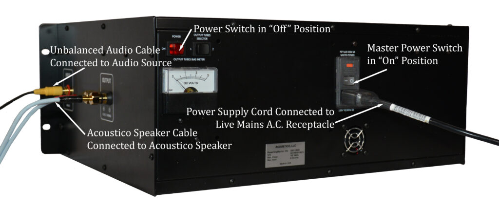
In order to apply the mains a.c. power to the amplifier, the power supply cord (included with the amplifier) should be connected to a live mains a.c. receptacle and a.c. power entry module on the back panel of the amplifier. The receptacle should provide 120V 50/60Hz mains a.c. power. Also, the master power switch on the a.c power entry module should be in the “on” position. The amplifier is now ready to be turned on using the power switch on the back panel (see picture below) or remote control (if equipped).
Get Help
If you have any questions regarding the product, or need assistance connecting the tube power audio amplifier to the speaker, audio source or the mains a.c. receptacle, please email Acoustico at eugenegrinberg@acoustico.llc.